In the design of the CAN node, we are usually more reliable for the communication of the bus and add various devices to the CAN interface. However, not all applications are needed. Excessive protection not only increases costs, but also the parasitic parameters of the device will inevitably affect the signal quality. This article will briefly introduce the role of the common mode inductance in the bus.
In practical applications, we see that many CAN products will use the common modulus inductance, but in conventional testing, we cannot see which indicator it has improved significantly, but affects the quality of waveforms.
In order to prevent reliability, many engineers will increase the full peripheral circuit to CAN. The CAN chip already has good anti -static, transient voltage capabilities, and some transceivers itself also has good EMC performance. In the application, we can increase protection, filtering and other peripherals according to design requirements.
For the CAN bus to add a common modulus induction, we mainly consider electromagnetic compatibility.
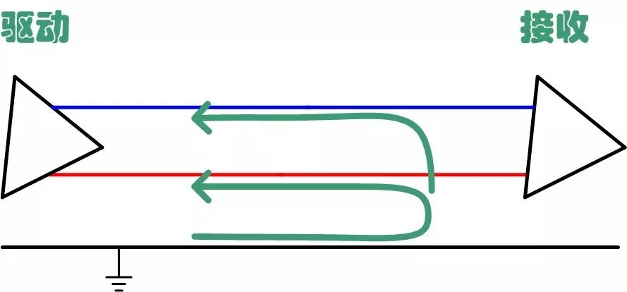
1. Together inductanceFirst introduce co -model interference. Figure 1. Figure 2 shows differentials and common mode interference and their transmission paths, respectively. The driver and receiver in the figure are transmitted by differential signals, similar to the CAN bus. Differential model interference is produced between two transmission lines, and co -mode interference is generated at the same time in the two lines. The potential is based on the ground.
Figure 1. Differential model interference and transmission path
Figure 2. Common model interference and transmission path
The co -mode inductance is on the upper and lower two -half ring of a magnetic ring, and the same turns are wrapped in the opposite coil. Common -mode interference is the same, so the magnetic lines formed in the magnetic ring are superimposed, and the inductance impedance is large to play a role in attenuation interference. The magnetic lines formed by the differential signal in the magnetic ring are offset each other, and there is no inhibitory effect. Only coil resistance and a small leakage have a slight impact on differential signals.
The co -mode inductance is essentially a two -way filter. On the one hand, the co -mode signal interference on the signal line is filtered, and on the other hand, the signal line itself does not send electromagnetic interference. The interference signals in FIG. 2 can be well suppressed by the co -modular inductance, while the differential signal has almost no effect.
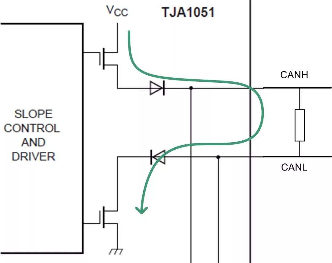
2. CAN bus characteristicsCANH and Canl inside the CAN transceiver are open source, and the output form is open, and the drive circuit is shown in Figure 3. This method can easily achieve the driver of the explicit level easily, while the hidden level is implemented by terminal resistance.
Figure 3. CAN transceiver driving circuit
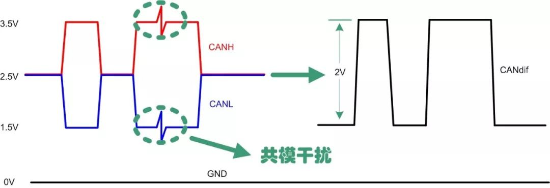
The inherent differential transmission form of the bus makes CAN have a good ability to suppress co -mode interference, as shown in Figure 4. Through the reduction of CANH and Can, it can eliminate co -model interference from the outside, but Canh and Canl are not ideal symmetry. The rapid rise of jumping edges will bring EMC problems.
We look at the bus waveform through the oscilloscope, test static electricity, EFT, waves, and no abnormalities in conducting harassment resistance. However, testing the transmission emission cannot meet the limit requirements, but the normal bus actually sends conduction interference outside the bus.
Figure 4. CAN transmission waveform
Third, why should I add a sense of inductance?For the EMC problem of the CAN interface, in addition to choosing better performance, the CAN transceiver chip required by symbols, another simple method is to increase the periphery of the CAN interface. The co -mode inductance is a good choice. In the existing car electronics CISPR 25 standard, there are very strict requirements for conduction harassment limit. Many CAN transceivers will exceed the limit.
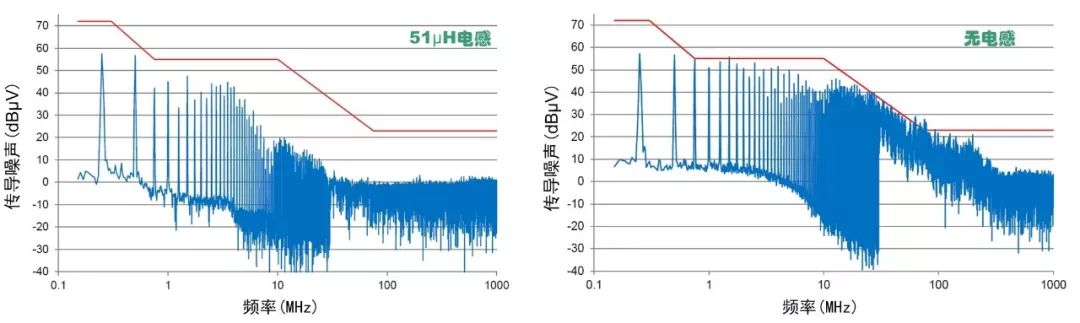
As shown in Figure 5, it is to conduct harassment of the CAN interface that increases the increase in testing and does not add a common modular inductance according to the vehicle regulations. The total electromotivity value is 51 μH. You can see that the noise improves in various frequency bands. Very heavy.
Figure 5. Express harassment test
The sense of co -mode inductance has a significant effect on reducing conduction harassment, which can help us quickly pass the test requirements and meet the requirements of existing car.
The co -mode inductance will inevitably have parasitic inductance, DC resistance, considering the number of bus nodes, communication distance and other factors, which will cause resonance and affect the quality of the bus signal. As shown in Figure 6, the green waveform is the bus waveform that increases the co -mode induction. There are obvious resonance on the signal decline.
In addition, the co -mode inductance sense is large, and the direct section is directly in the transistor interface. A short -circuit in the actual application and the heat insertion and other states will cause the consequences to generate a transient high pressure at both ends of the inductance, which will directly damage the transceiver directly.
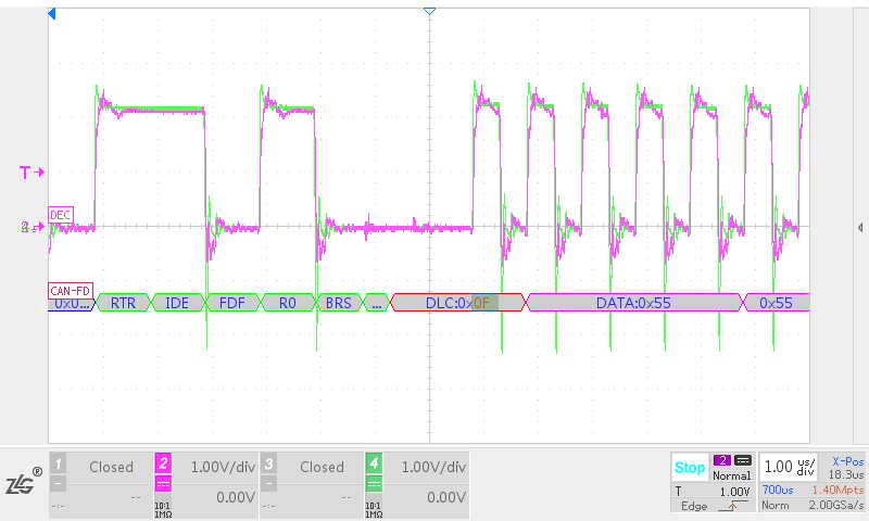
Figure 6. CAN waveform with added common mode inductance
4、 SummaryThe advantages and disadvantages of using common mode inductors for buses are quite obvious. It can filter out common mode electromagnetic interference in signal lines, attenuate the high-frequency part of differential signals, suppress the electromagnetic interference emitted by the CAN interface itself, and have a good improvement effect on conducted disturbances. However, its application still needs to consider the resonance and transient voltage it brings, which are unfavorable to the quality of bus signals in long-distance and multi node communication, For general industrial applications, there are no strict requirements for conducted emissions, so common mode inductors may not be added.
Source: 21ic official account